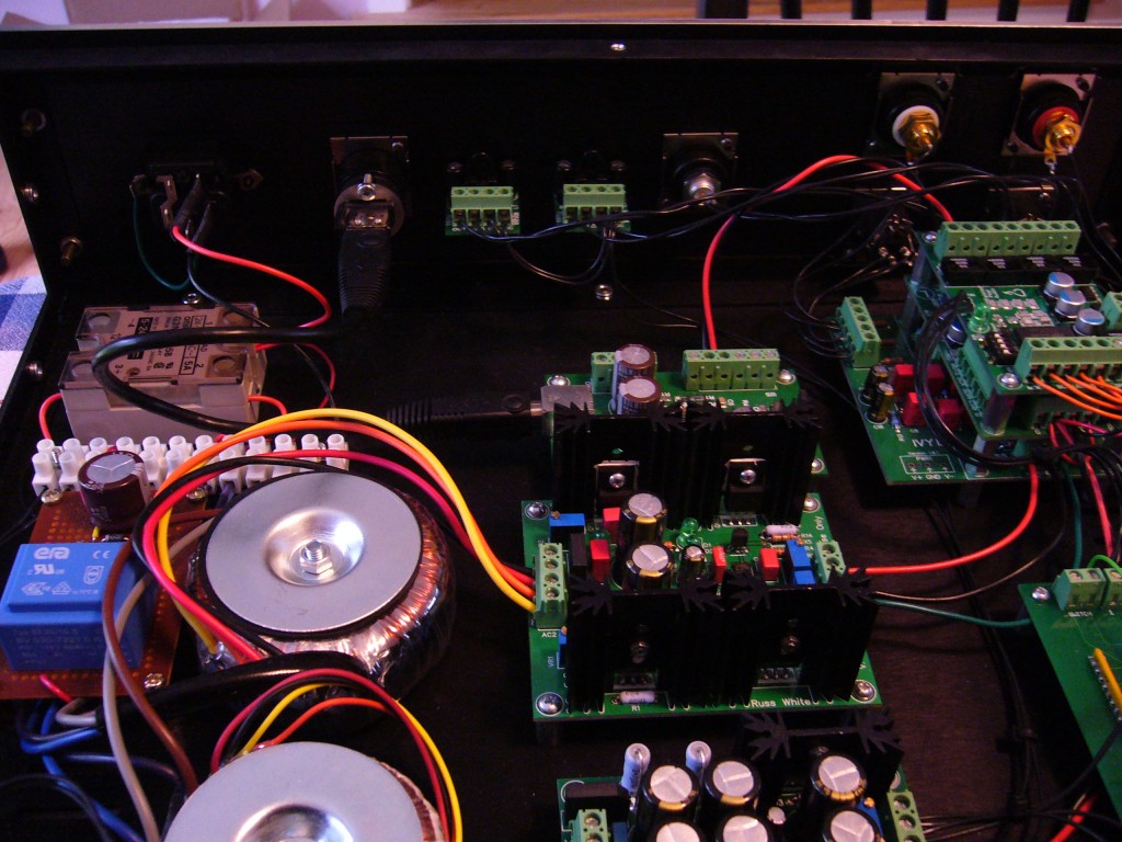
 A while back I built a Digital-to-Analog Converter (DAC) for my audio system. What it does in a nutshell is take the digital stream of data (one of the standards for a stream is S/PDIF) from a player and convert it into an audio signal. Today, most digital audio systems (CD players to computers and everything in-between) have a DAC internally. On nicer computers, this is what a sound card is primarily for. Building a stand-alone DAC enabled me to get the audio signal away from the noisy environment of most digital systems. On my old computer, I could actually hear noise when I opened and closed windows.
I built my system out of mostly Twisted Pear components including their 4:1 S/PDIF multiplexer (MUX for short). This allowed me to have four digital inputs to my DAC and switch between them at my leisure. The switching is done through a 4-wire interface: a ground wire, a voltage rail and two control wires. Anyone familiar with binary counting will understand how this works. Both controls grounded, or 00, selects the first input, 01 gets the second and so on.
Twisted Pear includes a rotary switch and wiring diagram to make a very simple way to switch between inputs. However, I didn’t want a knob on the front panel of my DAC, I wanted to have a button that you press and it cycles through the four inputs and have 4 LEDs to indicate which input is selected. Since the control interface uses a binary interface, my solution was to use a binary counter and have it cycle to the next value on a button press. A binary decoder would take the signal and light one of the LEDs. Simple and cheap. I worked out the circuit and had a nice little board made to make it look nice.
That was Version 1, V1.1 came when I realized I had nothing to compensate for the contacts inside the button bouncing. Every time the button pressed, the contacts make then break then make a circuit several times while the little metal pieces bounce around. The result is instead of switching to the next input on a button press, it would do so quite a few times, often ending up on the same input I was trying to switch off of. The solution I used to fix this was a circuit using a 555 timer as a monostable multivibrator. This way, regardless of how many times the button bounced, the 555 would fire off a set length pulse on the first bounce and after the pulse ends, the switch has stopped bouncing. It worked rather well and this is the system I have in the DAC now.
However, as time went by, I started noticing some weird behavior. If the fridge turned on in the house, the input would switch. If something needing a lot of power was running on the same power circuit, the input would just keep switching. After some careful thinking I arrived at what I suspect is the root of the cause. To make sure all the voltages are correct, I am running the counter, decoder, 555 and four LEDs off of the voltage on the 4:1 MUX. Based on the specs of the regulator in the MUX and how much I have running on it, I suspect I am drawing right near or above the recommended current amount. So when the power line fluctuates at all, the regulator can’t handle it, it drops the voltage a little and this triggers the 555 timer.
I finally decided I’ve had enough of this and I am in the process of coming up with a V2 controller circuit. The main change will be going to a separate voltage supply for everything that should be more stable than using the little overworked one on the MUX. The new circuit must be able to drop into my DAC with minimal changes so the board must have the same dimensions. The to-do list is as follows:
- Finalize the schematic
- Buy the parts needed
- Build the circuit on a breadboard and test with the DAC
- If it works, design the board and have it made
- Populate the board, test and install
As I progress, I will be posting updates. The goal for the next update is to have a detailed breakdown of the circuit.