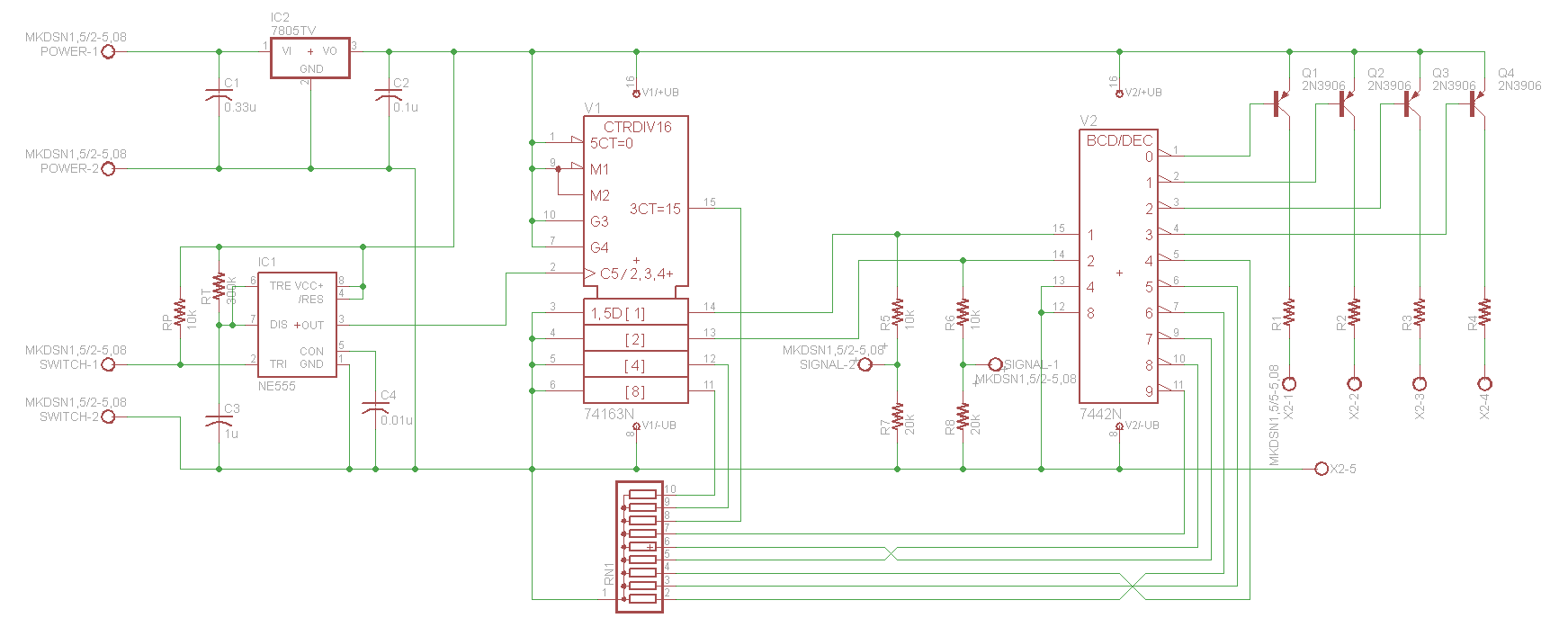
Last time, I described the problem I was having with my DAC control circuit. At that point, I was still working on the schematic and had yet to finalize the design. I finally came up with one I’m satisfied with and I’m going to step through the different blocks here.
The first and most essential block is the power regulator. The necessity for having one comes from the DAC not having a 5 volt power rail currently inside it. Since the case doesn’t have the space for one and it would only be used for the logic in the controller circuit, I decided to incorporate it into the circuit. There’s a number of different ways to drop existing voltage down to 5V but using a linear power regulator IC, like an LM7805, is a cheap, simple and very effective option.
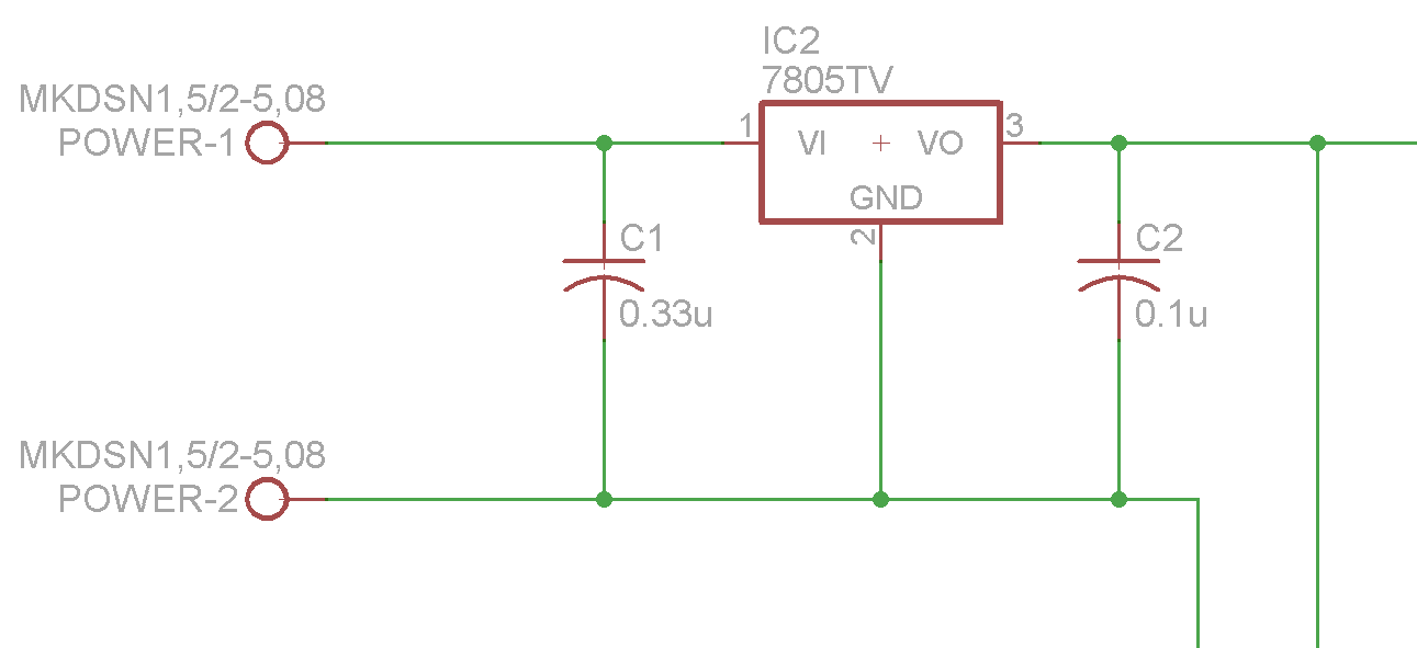
So that’s exactly what I did. I added capacitors on both input and output per the manufacturer’s recommendations in the spec sheet. I suspected it would not need a heatsink for the low amount of current I would be using. I did the calculations regardless and found my hypothesis to be correct.
The first block in the signal chain is the same 555 timer-based switch debounce circuit as before. The circuit is also called a monostable multivibrator and there is a considerable amount of literature available for it so I am not going to rehash what greater minds have written.
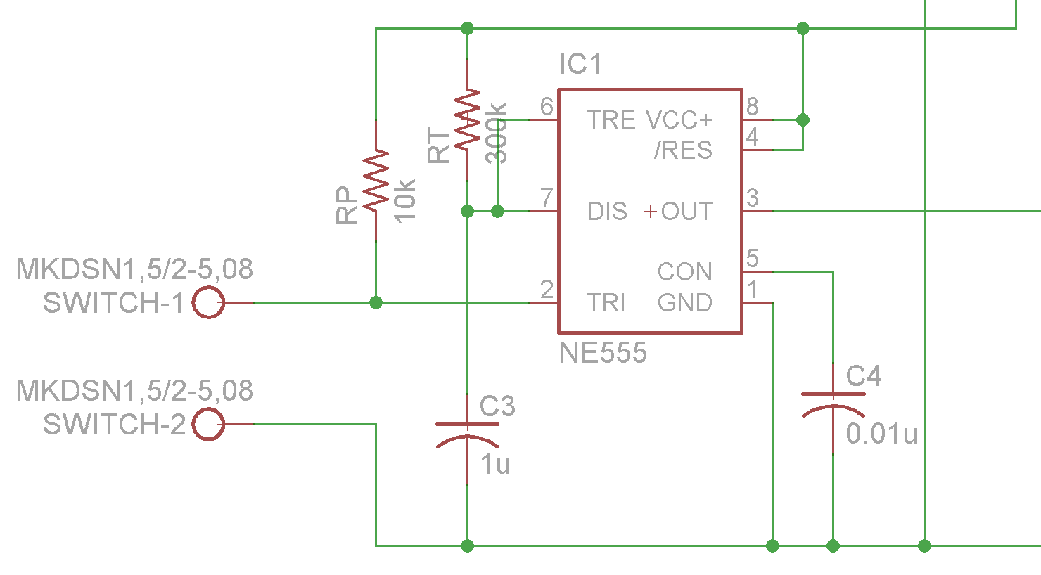
The specific values of the resistors and capacitors were chosen for a specific pulse time following the equation here. The signal from the switch on the DAC front goes into the trigger terminal on the block and output line goes onto the next block.
To get a cycling 2-bit signal needed to control the DAC MUX, I chose a digital counter to fulfill the duty. In the simplest terms, whenever a clock pulse is detected on that pin, the output pins increase by one binary value. Since I only need two bits for control, the two least significant bit pins are the outputs of this particular block.
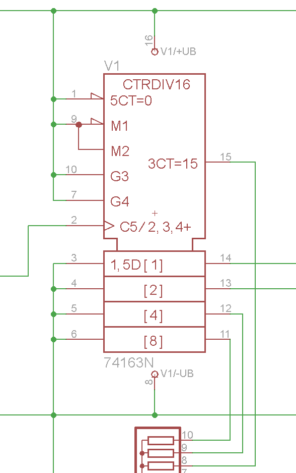
The specific counter I chose was a 74LS163 synchronous counter which uses TTL logic since I do not need the higher speed of different logic circuitry. The counter comes with a variety of extra controls defined in the data sheet which I set either high or low to suit this purpose. I have a thing against leaving logic outputs floating so I had all unused outputs of the counter connected through a resistor network to ground.
One of the problems I discussed before is that TTL logic outputs a 5V signal and the MUX accepts a 3.3V signal. The solution for this falls under logic level conversion and there are many options available. Once again, simplicity is the key and since I have two pins and they just need to be dropped a couple volts, a simple resistor voltage divider will do just perfectly.
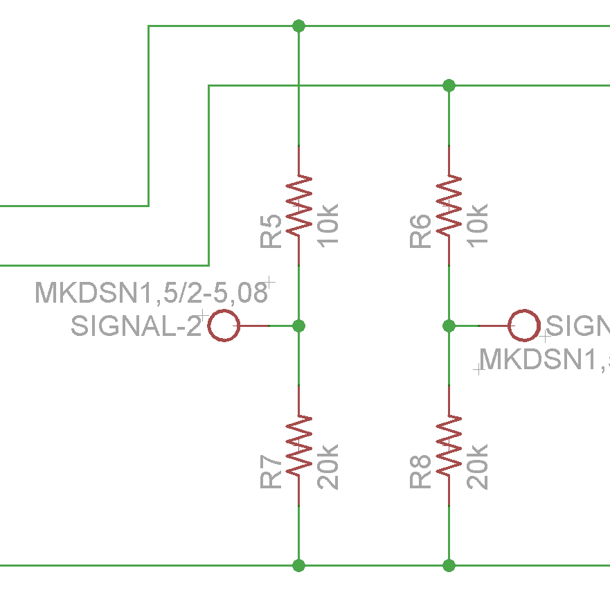
A voltage divider works in this configuration with the output being a fraction of the input voltage determined by the values of the resistors. I want the output to be 3.3V so by some simple algebra, R7 and R8 must be twice the value of R5 and R6. I am assuming current draw will be minimal to the MUX so I chose high values to reduce the current through the divider.
The final portion of the circuit is for controlling the LEDs. I have four LEDs that each indicates a particular input. To take the 2-bit signal from the counter and convert it into four independent signals, I am using another IC called a decoder. The decoder will output a signal on one of its pins based on the binary signal it receives on the input. Finally, for versatility, I added transistors to power the LEDs so that I am not limited by the output power of the decoder.
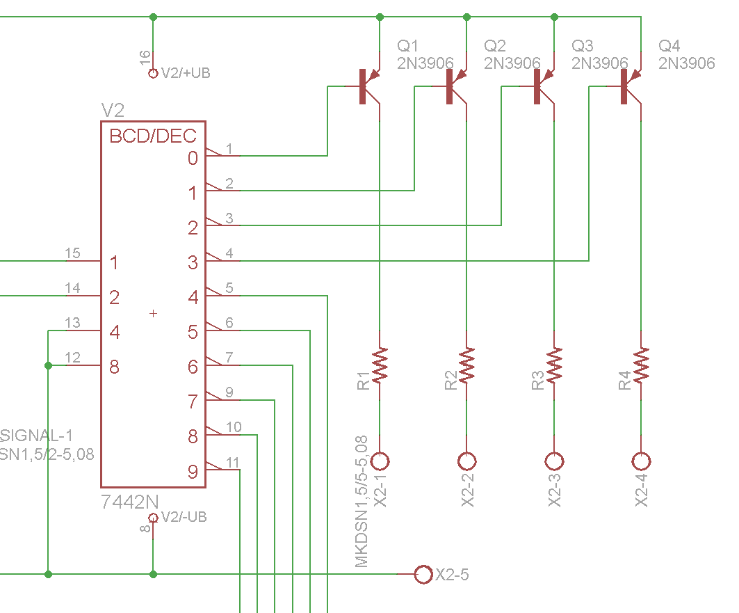
The particular decoder I chose was a 74LS42 4-bit decoder mainly for the reason that it is from the same family as the counter. It has four inputs and I do not need the two most significant bit inputs so those are tied to ground so they will not affect operation. The decoder also has six outputs I will not be using which I tied to the resistor network again. The two inputs I am using come straight from the counter and the four outs each have their own transistor. This particular counter outputs a low signal when an output is selected which necessitated PNP transistors for the LEDs. Each LED will have a terminal to connect to but all four will connect to one ground terminal to save space. The resistor values will be chosen based on the particular LED I feel like going with.
So that is the circuit in its entirety. The next step for me is putting it all on a breadboard and actually testing it. I already have the parts and I have a break coming up so I should be able to have it all tested and written up very soon.